

How to Choose the Right BMS Balancing Module for Energy Storage Systems
In a large-scale energy storage system, cell balancing is often treated as a secondary BMS function. In practice, it can become one of the main factors affecting usable capacity, charging time, thermal load, and long-term consistency between cells. Even when battery cells come from the same production batch, differences in capacity, internal resistance, self-discharge rate, and temperature can gradually increase the voltage and state-of-charge gap between cells.
For engineers selecting a subordinate BMS module, the key question is not simply whether the system uses passive or active balancing. The more useful question is: what balancing architecture matches the cell count, system voltage, battery capacity, thermal conditions, and required monitoring accuracy?
This guide explains how to evaluate BMS balancing modules for energy storage applications and how different channel configurations can affect system design.
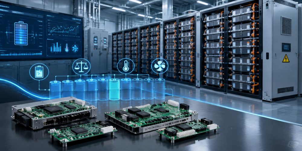
Why Cell Imbalance Becomes a Problem in Energy Storage
A battery pack connected in series is limited by its weakest cell or cell group. If one cell reaches its upper voltage limit earlier than the others during charging, the BMS may need to reduce or stop charging even though other cells still have available capacity. During discharge, the opposite problem can occur when a weaker cell reaches its lower voltage limit first.
The imbalance does not necessarily start large. A small difference can accumulate over hundreds or thousands of operating cycles because each cell experiences slightly different electrical and thermal conditions.
| Source of imbalance | Typical effect | Potential system impact |
|---|---|---|
| Manufacturing variation | Different capacity and internal resistance | Uneven SOC and voltage behavior |
| Self-discharge differences | Cells lose charge at different rates | Increasing SOC deviation during storage |
| Temperature variation | Different electrochemical performance | Uneven aging and resistance |
| Uneven current distribution | Different electrical stress | Localized degradation |
| Cell aging | Capacity and impedance gradually diverge | Reduced usable pack capacity |
This is why cell-level voltage and temperature monitoring should be considered together with balancing capability. A balancing circuit cannot compensate effectively if the BMS cannot accurately identify which cells are drifting.
Passive vs. Active Balancing: What Is the Real Difference?
Passive balancing removes excess energy from higher-SOC cells, normally through a resistive path. The energy is converted into heat. It is relatively simple, economical, and well suited to applications where the imbalance is modest.
Active balancing takes a different approach. Instead of simply dissipating excess energy, it transfers energy from higher-SOC cells toward lower-SOC cells through an active balancing circuit. This can reduce balancing losses and becomes more attractive as cell capacity and system scale increase.
| Parameter | Passive balancing | Active balancing |
|---|---|---|
| Energy handling | Excess energy dissipated as heat | Energy transferred between cells |
| Circuit complexity | Lower | Higher |
| Thermal load | Higher during balancing | Generally lower for equivalent transfer |
| Balancing efficiency | Lower | Higher |
| Cost | Generally lower | Generally higher |
| Large-capacity ESS suitability | Depends strongly on imbalance level | Strong candidate for demanding systems |
For example, if a 300 Ah cell has a 5% SOC difference, approximately 15 Ah of charge would need to be equalized. A low-current passive circuit can require many hours to remove this difference, while a higher-current active balancing architecture can transfer the required energy much faster. The actual balancing time depends on balancing current, control strategy, cell chemistry, operating conditions, and the starting SOC difference.
How Cell Count Changes the BMS Design
Channel count is one of the first specifications engineers should check when selecting a subordinate BMS module. A module designed for 48 cells cannot simply be treated as equivalent to a 112-cell monitoring module because both perform the same basic BMS function.
A higher channel count can reduce the number of monitoring modules required for a battery system, but it also increases wiring, measurement, isolation, communication, and thermal-management considerations.
| Example module | Channel configuration | Balancing type | Potential application consideration |
|---|---|---|---|
| ESBMM-4812 | 48-cell | Passive | Battery modules with moderate cell count |
| ESBMM-B212 | 112-cell | Passive | High-density monitoring with thermal control |
| ESBMM-A422 | 104-cell | Bidirectional active | High-density systems requiring active transfer |
| ESBMM-6412 | 64-cell | Passive | Medium-size battery modules |
| ESBMM-6012 | 60-channel | Passive | Custom energy-storage monitoring architectures |
The available module range illustrates an important design principle: channel count and balancing method should be evaluated together. A higher channel count does not automatically mean better performance. The correct combination depends on how the battery pack is physically divided into modules and how the BMS communicates with the upper-level controller.
When Passive Balancing Is Still the Practical Choice
Active balancing receives considerable attention because it can transfer energy instead of wasting it as heat. However, passive balancing remains practical for many battery designs.
A 48-cell Passive Balancing BMS Module can be a sensible option when the battery module has a manageable cell count, the expected cell mismatch is relatively small, and the additional cost and circuit complexity of active balancing are not justified.
Passive balancing can also simplify thermal and control design when the balancing current is limited and balancing mainly occurs near the end of the charging process. For applications where balancing energy represents only a small fraction of total stored energy, the simplicity of passive architecture may outweigh its energy loss.
The important point is to calculate the actual imbalance energy rather than selecting active balancing simply because it is technically more advanced.
Why High-Voltage ESS Requires More Careful Module Selection
High-voltage energy storage systems introduce additional requirements for insulation, voltage measurement, communication architecture, and fault management. A module designed for a high-voltage battery stack must be evaluated as part of the complete BMS architecture rather than as an isolated circuit board.
For example, the ESBMM-B212 is specified as a 1500 Vdc, 112-cell passive balancing slave module with thermal control. A 1500V 112-cell Passive BMS Module can therefore be considered when the system architecture requires a high channel count together with temperature-related monitoring.
| Design parameter | Questions engineers should ask |
|---|---|
| Maximum system voltage | Does the module support the intended DC voltage range and isolation architecture? |
| Cell count | How many series cells or cell groups must one slave module monitor? |
| Balancing method | Is passive balancing sufficient for the expected cell mismatch? |
| Temperature monitoring | How many temperature points are required and where should they be located? |
| Communication | How does the slave module communicate with the master BMS? |
| Serviceability | Can modules be replaced or diagnosed without extensive battery disassembly? |
When Active Balancing Becomes More Attractive
Active balancing becomes increasingly relevant when the battery capacity is high, cell mismatch is significant, balancing time is important, or the system operates frequently through charge and discharge cycles.
The main advantage is energy redistribution. Instead of converting excess charge into heat, the balancing circuit moves energy toward cells with lower SOC. This can be particularly useful for large-format cells, where even a small percentage difference represents a substantial amount of energy.
A 104-cell Bidirectional Active Balancing BMS architecture, such as the ESBMM-A422, is therefore more relevant when the design requires high-density cell monitoring together with bidirectional energy balancing.
Bidirectional balancing can also provide greater flexibility because the energy-transfer path is not limited to one direction. However, the engineer should account for the additional switching components, control requirements, electromagnetic considerations, communication requirements, and overall cost.
A Practical Selection Framework for ESS Engineers
Before choosing a subordinate BMS module, it is useful to calculate five basic parameters: cell count, maximum voltage, cell capacity, expected imbalance, and required balancing time.
| Step | What to calculate | Why it matters |
|---|---|---|
| 1 | Series cell count | Determines required monitoring channels |
| 2 | Maximum DC voltage | Determines voltage and insulation requirements |
| 3 | Cell capacity | Defines the energy represented by a given SOC mismatch |
| 4 | Expected SOC difference | Estimates how much charge needs to be balanced |
| 5 | Required balancing time | Helps determine whether passive balancing is adequate |
A simple engineering estimate is:
For example, if the estimated imbalance is 3 Ah and the effective balancing current is 0.3 A, the theoretical balancing time is approximately 10 hours. Real operating time can be longer because balancing current is not necessarily constant throughout the process.
What to Check Before Ordering a BMS Slave Module
For battery manufacturers, ESS integrators, and BMS developers, product selection should go beyond the headline channel count. Ask the supplier for the complete electrical and communication specification before finalizing the architecture.
| Specification | Recommended verification |
|---|---|
| Cell voltage measurement | Accuracy, measurement range, and sampling method |
| Balancing current | Nominal and maximum current under actual thermal conditions |
| Temperature monitoring | Number of channels and supported sensor type |
| Operating voltage | Maximum DC voltage and isolation requirements |
| Communication interface | Protocol, communication rate, and master-BMS compatibility |
| Protection functions | Overvoltage, undervoltage, overtemperature, and fault handling |
| Mechanical integration | Dimensions, connectors, mounting method, and thermal environment |
| Customization | Channel configuration, firmware, communication, and connector options |
Matching the BMS Module to the Battery Architecture
There is no universal balancing solution for every energy storage system. A 48-cell passive module may be the better engineering choice for a compact battery architecture where cost, simplicity, and reliability are priorities. A 112-cell module can reduce the number of slave boards required in a higher-density configuration. For systems where balancing energy and balancing speed are major concerns, a 104-cell bidirectional active architecture may provide a stronger technical fit.
The best selection starts with the battery rather than the BMS product name. Define the number of cells, voltage range, cell capacity, thermal conditions, expected mismatch, balancing time, and communication architecture first. The BMS module can then be selected according to measurable system requirements rather than simply choosing the highest channel count or the most advanced balancing technology.